From our previous central force problem, we classified three different types of possible orbits: 1) unbounded orbits, 2) bounded elliptic orbits, and 3) bounded circular orbits. For this assignemnt, we will try to plot some of these orbits by integrating the first integral of motion,
where E is the total energy of the system and the right hand side is simply the sum of the effective potential energy
and the kinetic energy of the system. By rearranging the terms and solving for the radial velocity, we have
Since the angular momentum is also a constant of the motion, we can write
.
This gives us a relation between the differential change dt and the corresponding change dq
.
Substituting this into Eq. (1), we can eliminate dt from the equation. Then, by writing the r dependence explicitly and integrating the equation, we have
,
where r0 and q0 are the initial radial and angular position of the orbit. This equation can then be numerically integated to get the equation of motion for a particular orbit with a given energy E and angular momentum l.
For this problem, we again assume the following form for the interaction potential U(r)
and we take l2/2m=0.01, k=1, a=0.2. Then, do the following:
- Unbounded orbit (E=+10): Taking the following initial condition for the orbit,
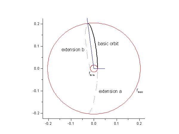
numerically integrate Eq. (2) to r=rturning using the Simpson's rule. The orbit will be given in polar coordinate by (r,q) calculated from this procedure. Note that the integrant is singular at r=rturning but the integral with rturning as one of its limit points remains well-defined*. This procedure will give the incoming branch of the orbit and the outgoing branch can be also be easily obtained by symmetry. In particular, the orbit is symmetric with repect to its q coordinate at the turning points. Plot the complete orbit including its incoming and outgoing parts for this case.- Bounded elliptic orbit (E=-10): Similar to the unbounded case, the orbit is invariant under reflection about the apsidal vectors - the vector connecting the center of force and the turning points (see the following figure).
Notice that the two extensions are reflections of the basic orbit about the two blue apsidal vectors. However, for the choice of our U(r), the bounded orbits will not be closed. They will form "spirograph" patterns within an annulus domain defined between rmin and rmax. For this part of the problem, you can first construct the basic orbit by integrating Eq. (2) between rmin and rmax using the Simpson's rule. [Note: Integrals with limits of integration starting or ending at rmin or rmax will be close to improper*. One should consider on how to effectively in dealing with them.] Then, the other extensions can be constructed by reflecting the basic orbits (and other extensions) about the apsidal vectors. For a visually pleasing result, you should plot at least seven or eight extensions.- In the bounded orbit case, will the orbits in general be closed (meaning that will it close on itself after a finite number of loops)?
Your answers are required to be accurate up to single precision.
*This is an example of a treatable improper integral. If one of the limit of the integral is exactly on the turning point, an open formula should be used. However, in our case, the square-root term in the denominator is only approximately zero since the turning point was approximated by another numerical method. Thus, the simple Simpson's rule will work in this case. On the other hand, the integrant still varies greatly near this turning point so that many subdivisions for the Simpson's rule might be needed to get to a desired tolerance. One should note that in plotting the orbits, you have the freedom in choosing the starting points and you can use this freedom to minimize the problems with imporper integrals. We will discuss the proper treatment of singularity in more detail in the next lecture.
Other related links on central force orbits: at Queen's Univ and at UMD
SolutionThe implementation of the solution in C can be found here. Since the Simpson's rule will typically require many subdivision if one of the intergal's limits is near a singluar point, an efficient strategy is to start the plotting away from the turning points and move toward them. In this way, only the a few integrals will be close to "improper" (with limits pts close to the turning points). For the unbounded orbit, one may start with r=1 and move toward rturning. The outgoing orbit is symmetric to the incoming orbit with respect to the turning point. In particular, If our incoming orbit is given by the sequence of points {ri,qi} for i=0,...,N, then the outgoing orbit will be given by the sequence of points {rN-i,qN+(qN- qN-i)}. For the bounded case, one should start at a midpoint between rmin and rmax and use two separate Simpson loops to move the orbit toward the respective turning points. If we start plotting from the turning points, all integrals will be close to imporper and the Simpson's Rule might take many steps.
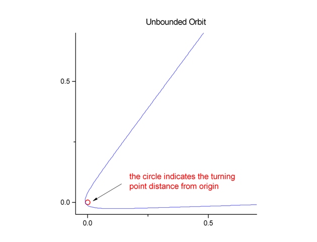
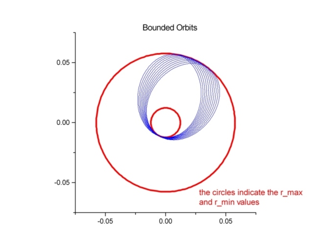
The followings are the graphs for the unbounded and bounded orbits. There are 200 data points for the basic orbit in each case. The unbounded orbit is with one extension and the bounded orbit is with 20 extensions.
The red circles indicate the radial locations of the turning points. The unbounded orbit travels from r=1 toward the center of force and then it scatters away from the center of force at its closest approach at r=rturning (the small red circle). The bounded orbit is forever restricted to move between rmin and rmax (the two red circles). The resulting pattern is similar to a spriograph. However, the bounded orbit is not closed. It will never retrace its own path. This is a result of the Bertrand's theorem which stats that the only types of central force capable of producing closed orbits independent of initial conditions are either an inverse-square force law or a hook-type force law.
As we will learn later, dealing with the differenial equations directly and solving them with a ODE solver will be a more efficient method to plot these orbits.
Consider a particle in a one dimensional box defined by the following potential:
The eigenfunctions and allowed energy levels of a free particle in this box will be given by the time independent Schrodinger equation
where the unperturbated Hamiltonian is given by
For the unperturbated potential V(x) chosen, the enigensolutions {En0, jn0} are simple to solve (see any introductory QM books).Now we suppose that the box is slightly perturbated by a weak potential,
withand V'=0 outside the well. The perturbed Hamilton H=H0+V'(x) defines a new set of eigenfunctions {jn} and eigenenergies {En}. One can use first order perturbation theory to approximate these quantities as
Putting this approximation back into the time independent Schrodinger equation and keeping only first order perturbed terms, we arrive at the following equation,
(1)
Evaluating the expectation values on both sides of the above equation, i.e. applyingto both sides and knowing that the unperturbated eigenfunctions are orthogonal, we can write down the following expression for the first order energy shift due to the perturbation,
(2)
NOTE: For this problem, the three unpreturbed bounded eigenstates (1 odd and 2 even) for this square-well potential are the same as in your previous assignment.
For this problem, take
, a=1, V0=10 and Vp=0.01 and do the following:
- Using a zero finding algorithm (e.g. Newton's method), find the energy of the three bounded eigenstates (1 odd and 2 even) for the unpreturbed square-well potential.
- Derive the theoretical results for the first order perturbation theory: Eq. (1) and Eq. (2).
- Write a code using the Romberg's Scheme with Trapezoid rule to find the first order energy shift E'n for the first three energy states (indicated by n=1,2,3) using Eq. (2).
NOTE:
The extrapolating table for the Romberg's Scheme should look like the following: The iteration formula stays the same as given in class.
k=0 k=1 k=2 h(m=0) T0,0 h/2(m=1) T1,0 T1,1 h/4(m=2) T2,0 T2,1 T2,2 Solution
The conditions for the eigen-energies are given by
and

for the even and odd states respectively where.
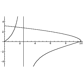
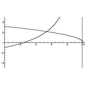
The solutions of these transcendental equations can be solved by Newton's Method. As we have seen from the previous exercies, the choice of the intial guess is important in the effectiveness of the Newton's method. The best way to obtain a good estimate is to graph the function using a graphic package.
Even States: sqrt(E)tan(sqrt(E)) and sqrt(10-E) vs. E
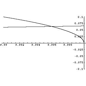
The following is a magnification of the second root for the even state with E~10.
Odd State: -sqrt(E)cot(sqrt(E)) and sqrt(10-E) vs. E
An ANSI C implemention of the Newton method to find the roots of these equations is given here. (Note: The basins for the first even and odd roots are big and any initial conditions roughly near them will converge to them. However, the second even root has a much smaller basin and its basin is near the boundary (E=10) where sqrt(10-E) ceases to be a real number. Here, a graphical suggestion will help to provide a good guess.) Remember that the exponentially fast convergence of the Newton's Method is only effective if we have a valid initial guess.
A sample output from the ANSI C program is given here and the eigen-energies are given by
Ee1=1.40721472477016
Ee2=9.99598073754667
Eo=5.37580591367022.
An analytic derivation of Eq. (1) and Eq. (2) can be found in the following link. (The file is in pdf format.) The energy shifts correspond to the even and the odd states and can be written in integral form as follows (a=1):
,
where A and B are the normalization constants for the even and odd eigenfunctions respectively. The integrals for the perturbed energy can then be carried out using the Romberg's Scheme
k=0 k=1 k=2 h(m=0) T0,0 h/2(m=1) T1,0 T1,1 h/4(m=2) T2,0 T2,1 T2,2
The first column is the "raw" results using the simple Trapezoid rule. An improved result T1,1 using a step size of h/2 can be constructed from the two "raw" values T0,0 and T1,0. The iterative formula (Romberg's Scheme) to do this extrapolation is given in class
.
One preceed to obtain better and better estimates with smaller step sizes by going down the above triangular table using the above recursive formula. To terminate the procedure, one can compare the difference between the current estimate Tk,k with the next estimate Tk+1,k+1. The program should stop if this difference is less than a prescribed accuracy level. This difference can also serve as the error estimate for the integration procedure.
An ANSI C implementation of this algorithm is given here and the output of this program is here.
Let consider a conducting sphere with radius a. On the surface of this sphere, a potential V(q) possessing azimuthal symmetry is maintained. Using spherical coordinates, the general solution for the potential F (r,q) inside the sphere can be written as an expansion of the Legendre polynomials:
The coefficients An are found by imposing the boundary condition (V(q) on the surface of the sphere) on Eq. (1). This gives,
Then, by using the orthogonality condition for the Legendre polynomials, these coefficients can be written in terms of the following intergal,
For this problem, we will assume that V(q)=e-cos2q (note: the exponent is minus of the square of cos q instead of -cos 2q) on the surface of the sphere and you need to perform the following tasks: (take a=1)
NOTE: The recurrence relation for the Legendre polynomials is given by
- Use the recurrence relation given in class (also see below) and the initial conditions, P0(x)=1 and P1(x)=x, to write a subroutine which can evaluate the higher order Legendre polynomials.
- Pick your favorite integrator and write a subroutinue which can calculate the coefficients given by Eq. (3).
- Determine the number of coefficients needed so that the boundary condition Eq. (2) is satified up to single precision.
- Use the coefficients obtained from previous steps to plot the electric potential F(r,q) inside the sphere as a function of r and q.
.
Solution
The implementation of the recursion relation to calculate the Legendre polynomials is quite straight forward. The integrator chosen for this problem is the Simpson's rule. There are two simplications which one can make. First, the integral over q in Eq. (3) can be simplified by the change of variable x=cos(q),
.
Second, since V(q) is an even function, the integral above will be zero for n=odd. Thus, An=0 for n=odd. A C code which calculates the coefficients is given here. The infinite series in Eq. (2) is a statement of completeness for the Legendre polynomials in the range [-1,1]. Numerically, we need to truncate the series so that the equality is satisfied up to single precision. In this case, we can check this condition for a typical point x in the interval [-1,1] and a value of n=12 works for this case.Here is a graph of the calcuated potential and the maintained potential at r=1.
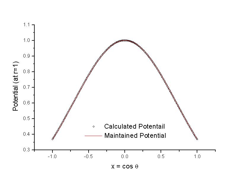
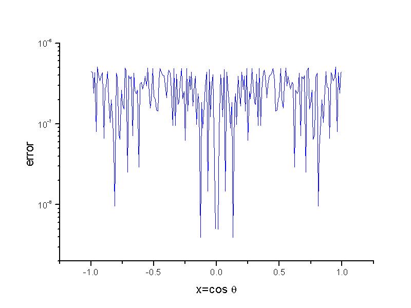
As one can see from this graph, the boundary condition is satified quite well. Quantitatively, this agreement can be seen by plotting the absolute error between these two quantities. The error for all theta values is within the required single precision.
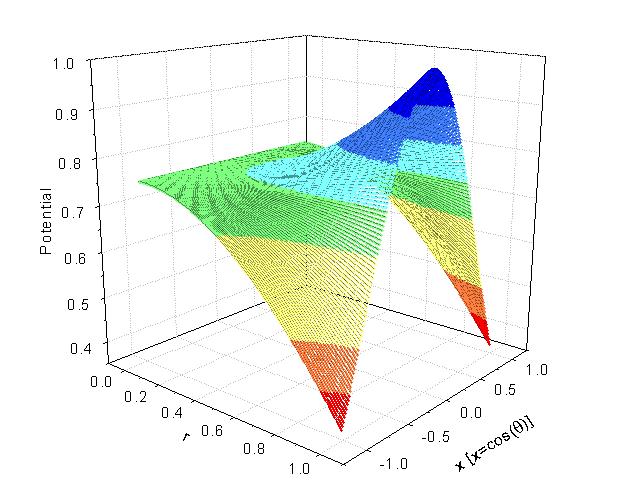
The following is a 2D plot of electric potential F(r,x=cos(q)) within the sphere.
